Introduction
A solar mounting structure is the backbone of any photovoltaic (PV) project. It supports the solar modules, transfers loads safely to the roof or ground, and ensures the system can operate reliably for 25–30 years. Choosing the right structure is not simply a matter of selecting rails and brackets — it requires careful calculation based on site conditions, module specifications, environmental loads, and engineering standards.
An incorrectly designed mounting system can lead to excessive material costs, installation problems, or even structural failure under extreme wind, snow, or seismic events. This guide explains the key steps engineers use to calculate the correct solar mounting structure for a PV project.
1. Understand the Main Loads on a Solar Mounting Structure
The first step is identifying all forces acting on the PV mounting system.
1.1 Dead Load (Permanent Load)
Dead load is the weight of all fixed components, including:
· Solar panels
· Aluminum rails
· Clamps
· Bolts and fasteners
· Mounting brackets
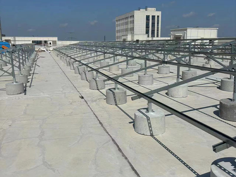
· Ballast (for some flat-roof systems)
The structure must safely support this weight throughout the project lifetime.
Basic formula:
Dead Load = Module Weight + Mounting System Weight + Additional Equipment Weight
Example:
A PV module weighs 25 kg and has an area of 2.2 m²:
\[ 25kg ÷ 2.2m² = 11.4kg/m² \]
Then add the weight of rails, clamps, and other components.
2. Calculate Wind Load
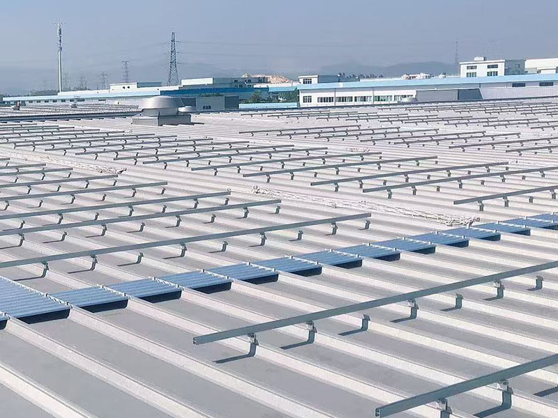
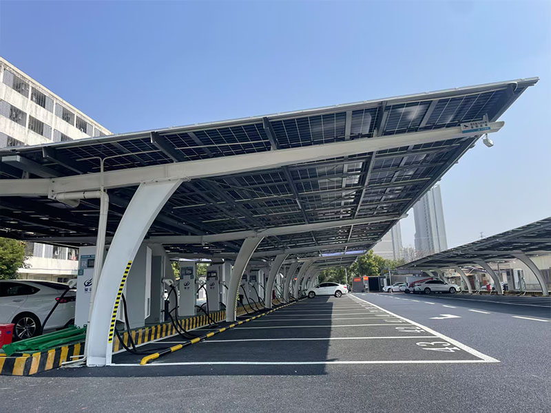
Wind load is usually the most critical factor in solar mounting design, especially for rooftop systems, ground mounts, and solar carports. Wind creates pressure and uplift forces that can pull modules and structures away from their foundations.
Basic Wind Pressure Formula
\[ P = 0.5 \times \rho \times V^2 \]
Where:
· P = wind pressure (Pa)
· ρ = air density (approximately 1.225 kg/m³)
· V = design wind speed (m/s)
Example:
For a wind speed of 40 m/s:
\[ P=0.5 \times 1.225 \times 40^2 \]\[ P≈980Pa \]
The actual design load must also consider:
· Wind direction
· Panel tilt angle
· Building height
· Terrain category
· Array edge effects
· Local design codes
Wind pressure is often higher at the edges and corners of PV arrays because airflow creates stronger suction forces in these areas.
3. Calculate Snow Load (If Applicable)
For projects in cold climates, snow load can become the controlling design factor.
Snow load depends on:
· Ground snow load
· Roof or panel tilt angle
· Snow density
· Snow drifting conditions
Basic formula:
\[ Snow\ Load = Ground\ Snow\ Load \times Shape\ Factor \]
For example:
If the local ground snow load is:
1.5 kN/m²
and the panel shape factor is:
0.8
Then:
\[ 1.5 \times 0.8 = 1.2kN/m² \]
Snow accumulation is usually greater on low-angle PV systems, while steeper modules may shed snow more easily.
4. Determine Solar Module Layout
The mounting structure depends heavily on the PV array design.
Important parameters include:
Module Information
· Length
· Width
· Thickness
· Weight
· Frame type
· Clamp position
Array Layout
· Number of modules per row
· Number of rows
· Row spacing
· Tilt angle
· Orientation (portrait or landscape)
Example:
A 1 MW ground-mounted project may require thousands of modules. Small changes in rail spacing or pile spacing can significantly affect steel consumption and installation costs.
5. Select the Correct Structural Components
After calculating loads, engineers select suitable components.
Aluminum Rails
Check:
· Bending strength
· Deflection
· Span length
· Material grade
Longer spans require stronger rails or closer support spacing.
Clamps
Clamps must withstand:
· Module weight
· Wind uplift forces
· Thermal expansion
· Mechanical stress
The clamp position should match the module manufacturer's requirements.
Posts and Foundations
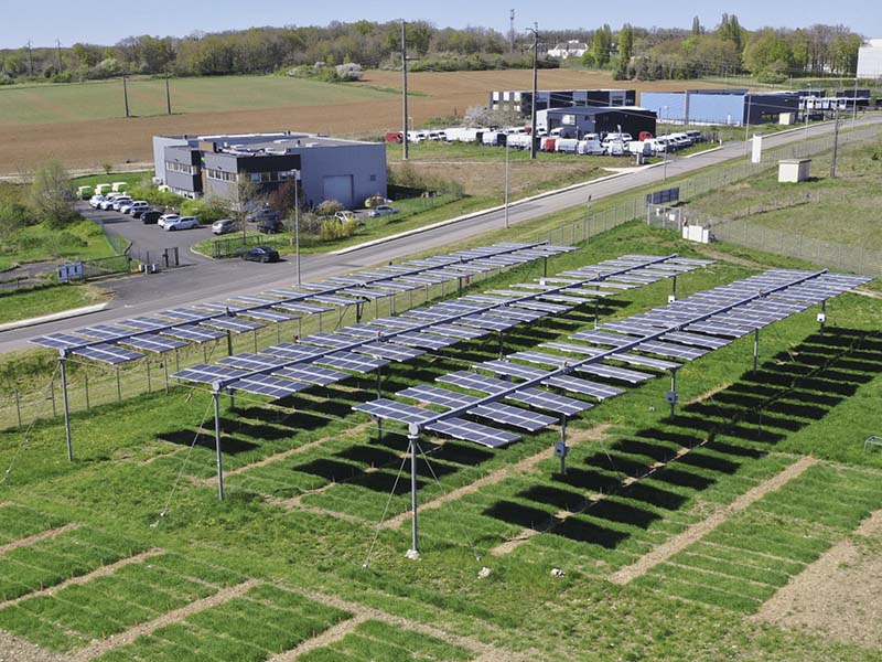
For ground-mounted systems:
Engineers calculate:
· Axial compression
· Pull-out force
· Bending moment
· Soil resistance
Foundation selection depends on:
· Soil type
· Wind speed
· Array height
· Ground conditions
Common foundation types:
· Driven piles
· Ground screws
· Concrete foundations
6. Apply Safety Factors and Design Standards
Solar mounting structures must follow local engineering standards.
Common standards include:
· ASCE 7 (United States)
· Eurocode
· AS/NZS standards
· GB standards (China)
The calculation normally includes:
· Load combinations
· Material safety factors
· Connection strength checks
· Deflection limits
For example, wind, snow, and dead loads are combined according to the applicable structural code rather than simply added together.
7. Example: Simple Ground-Mount Calculation
Assume:
· Module size: 2.2 m²
· Module weight: 25 kg
· Wind speed: 40 m/s
· Tilt angle: 25°
· Snow load: 0.8 kN/m²
Step 1: Calculate Dead Load
Panel:
\[ 25kg ÷ 2.2m²=11.4kg/m² \]
Add mounting structure:
\[ 11.4+4=15.4kg/m² \]
Step 2: Calculate Wind Pressure
\[ P=0.5×1.225×40^2 \]\[ P≈980Pa \]
Apply aerodynamic coefficients depending on array position.
Step 3: Select Structure
Based on the final loads:
· Choose rail size
· Determine clamp spacing
· Calculate pile depth
· Verify bolt strength
The final design should pass structural calculations before construction.
8. Common Mistakes When Choosing Solar Mounting Structures
Mistake 1: Using a Standard Design Everywhere
A structure designed for a low-wind area may fail in a coastal or hurricane region.
Solution: Always use project-specific wind and snow data.
Mistake 2: Ignoring Edge Zones
The first and last rows experience higher wind forces.
Solution: Reinforce edge areas or adjust spacing.
Mistake 3: Oversizing the Structure
Too much steel increases project cost.
Solution: Optimize:
· Rail spacing
· Material thickness
· Foundation design
Mistake 4: Choosing Based Only on Price
A cheaper mounting system may use:
· Thinner aluminum
·